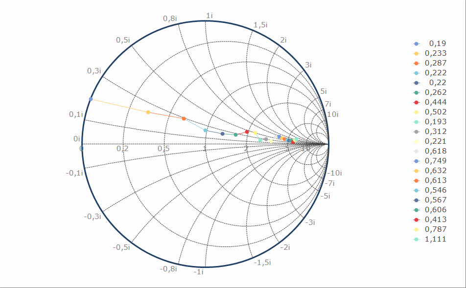


When working with transmission lines, a main concern is the SWR. The SWR is determined with the expression: If the load is matched to the line and generator impedance, the load will absorb all of the power there will be no reflections back to the generator. Z L is the load impedance and Z O is the characteristic impedance of the transmission line. This is the ideal condition so that all of the generator power gets to the load and any reflections will not interfere with the generator. The center point on the R line represents an SWR of 1. If you trace a line from that center point down so that it intersects with the SWR scale, you see that the value is 1. If the load doesn’t match the line and the driving generator, there will be reflections back along the line. As a result, the load doesn’t receive all of the power. Assume an SWR of 2.5 is determined, which is shown as a circle on the chart (Fig. 1, again).Īround the perimeter of the chart are additional scales that represent wavelengths. One complete rotation (360 degrees) represents 0.5 wavelength at the operating frequency. The Smith chart also can be used with admittance (Y), susceptance (B), and conductance (G), with units in siemens (S): One scale is called TOWARD GENERATOR and the other TOWARD LOAD.Īt the bottom of the chart, the scales are SWR, reflection coefficient, and return loss.


 0 kommentar(er)
